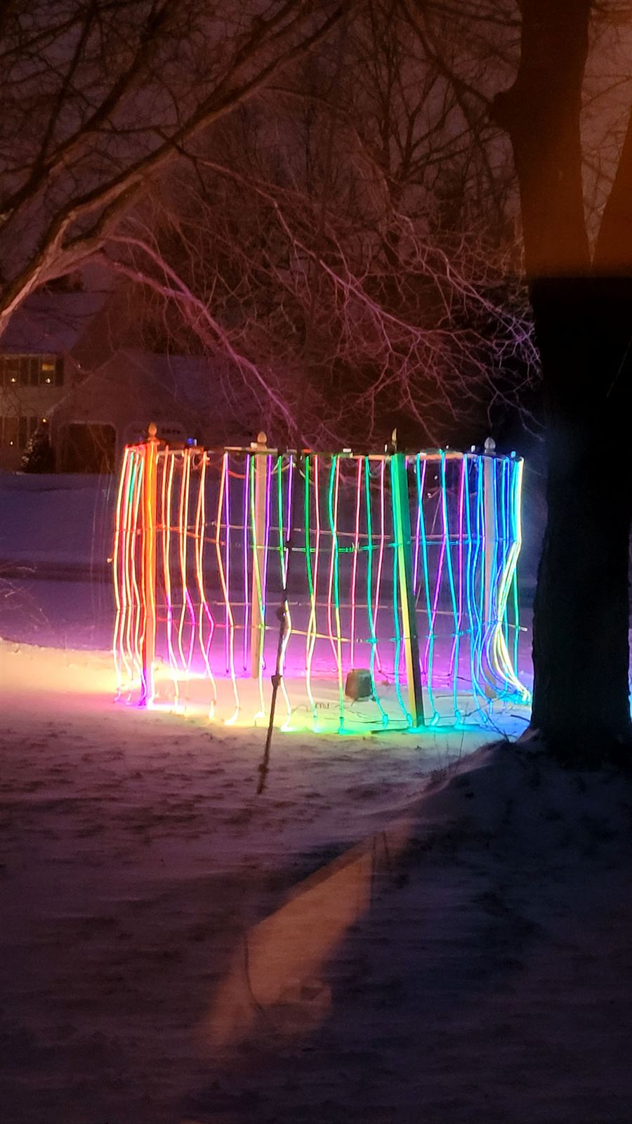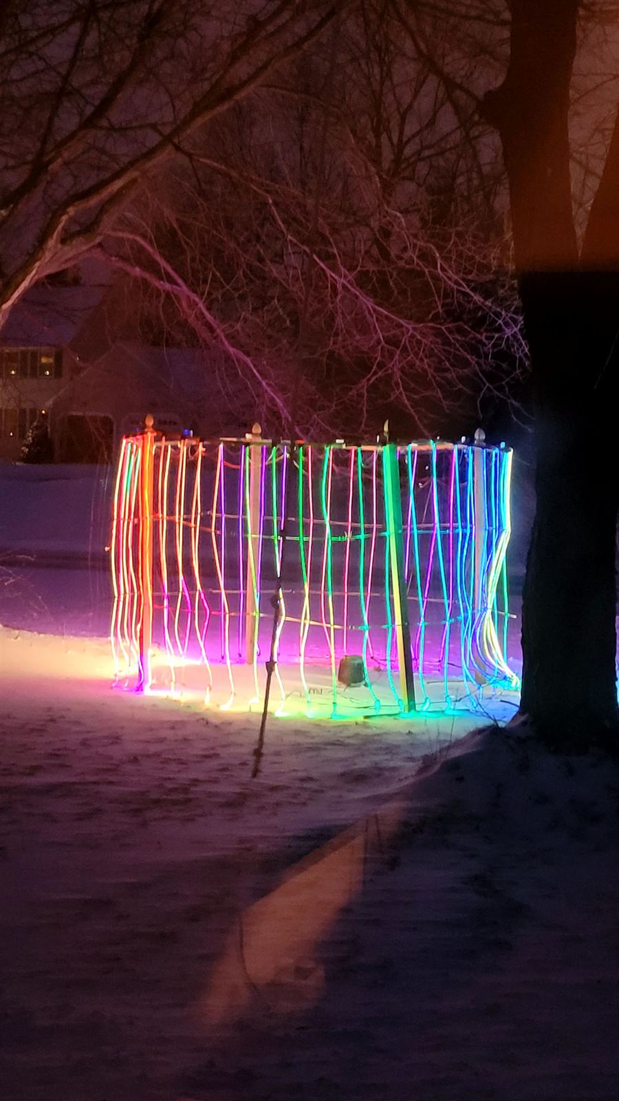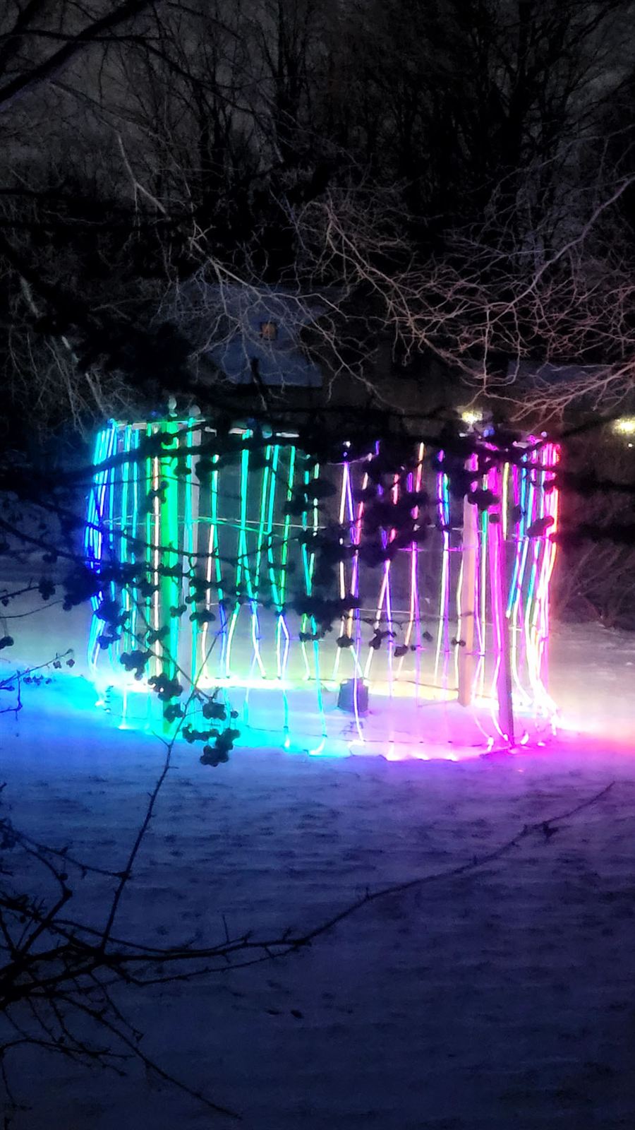
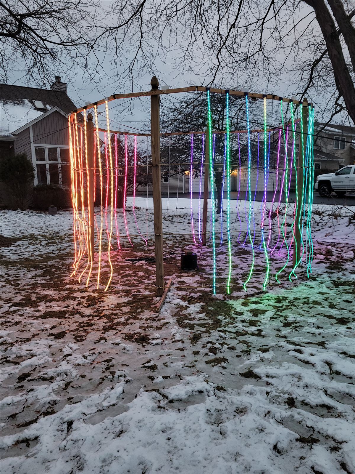
A ten-foot-tall, twenty-foot-diameter ring of light in the front yard — and anyone on the internet can take the controls.
Live nowThe ring is online. The simulator runs year-round, and the controls are open to anyone on the internet — right now.
Take the controlsThe lightshow project began from four motivations. First, I wanted to see how much weatherproofing I really needed to put some electronics reliably outside in the Western New York weather. I had a few 3D printed parts that were surviving quite well outdoors and a lot of the outdoor electrical housings I’ve seen can be quite minimal on waterproofing. Second, I wanted to build a little physics engine for fun. I’ve always loved physics and it has some really neat math and trigonometry, and I hadn’t had a solid opportunity to play with sines and secants since doing GIS work for the State of South Dakota. Third, I wanted to test the WiFi bandwidth and performance of cheap ESP-01 wireless microcontroller boards. And fourth, I wanted to do something a little unique for my holiday lighting on my house.
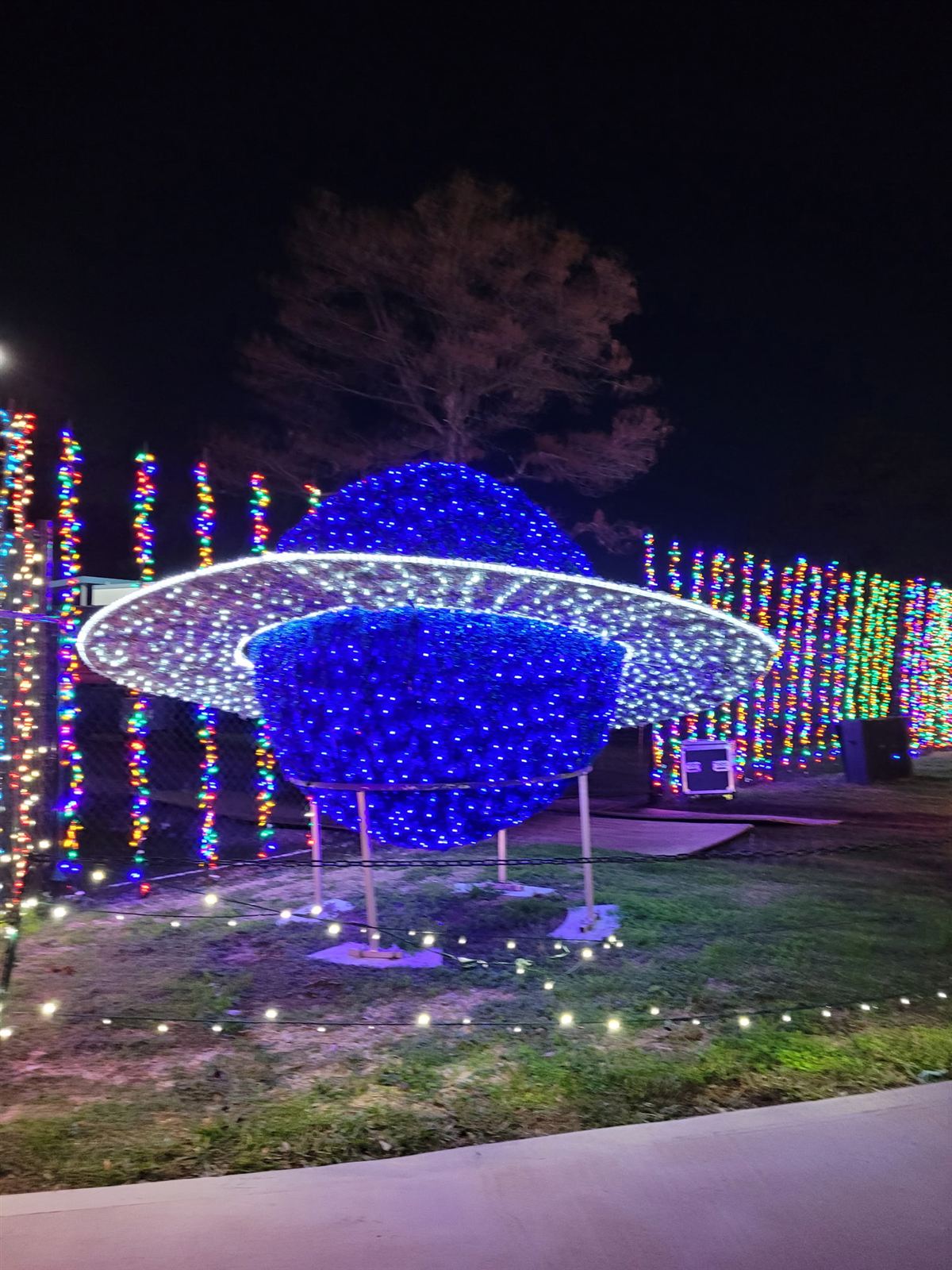

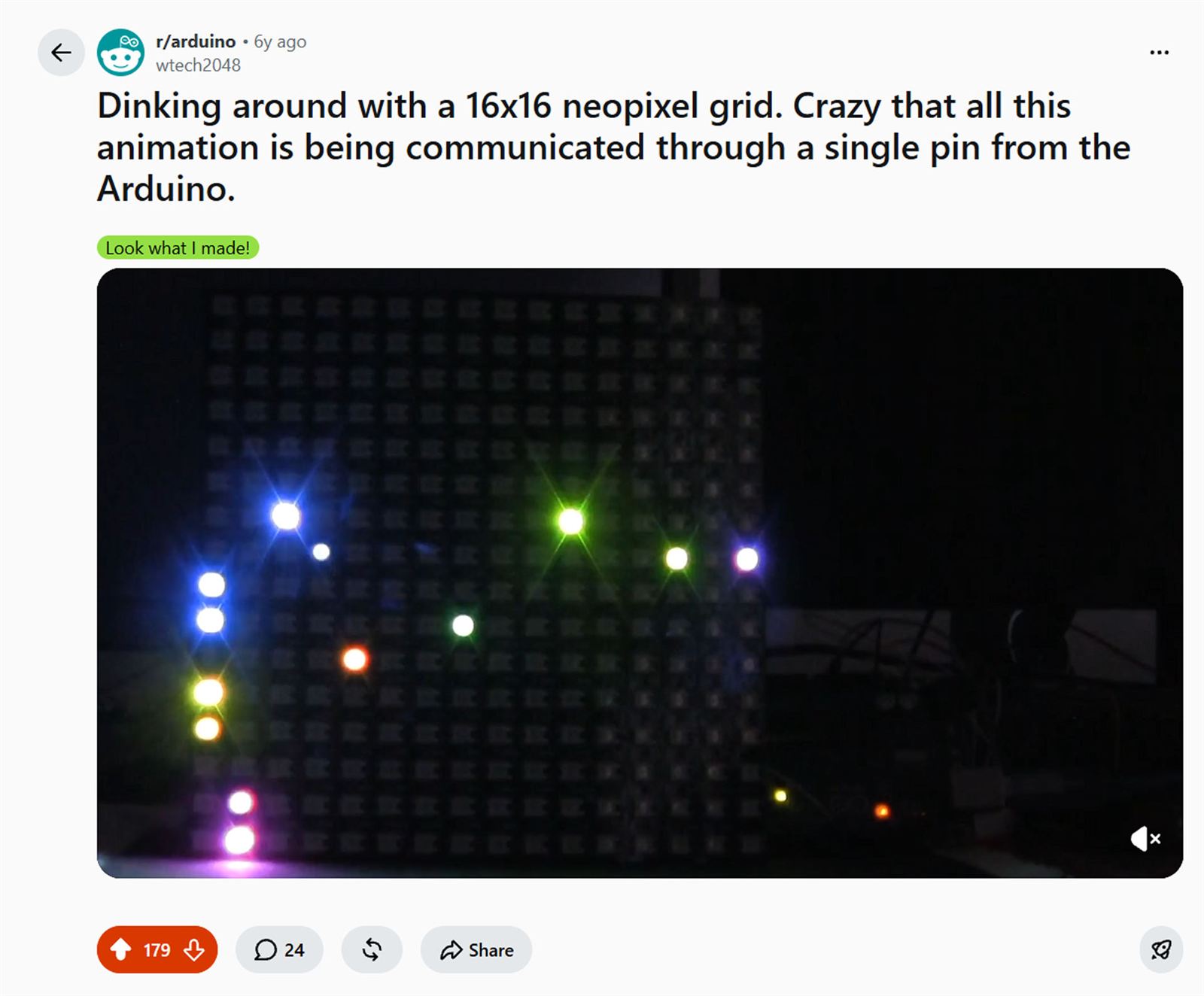
I had some background messing around with RGB LEDs. I played with a little 16x16 LED matrix in the past, goofing around with an Arduino Nano to draw some simple animations. I made a little fireworks show for it, and it even got a few updoots on Reddit’s Arduino sub. Today, the matrix is sitting on my workbench in the basement, siphoning a little power from my 3D printer, still playing the last fireworks program I made for it.
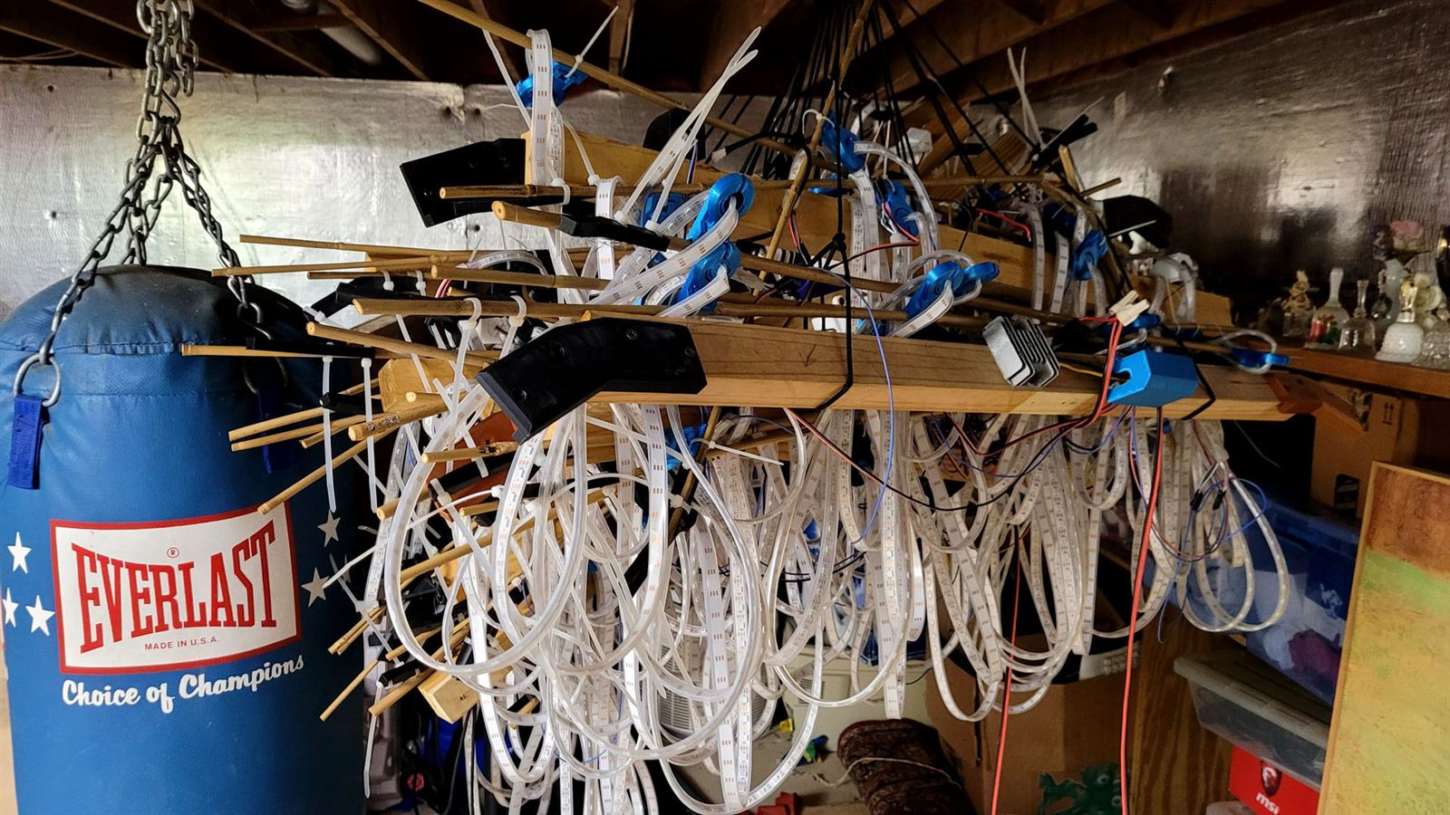
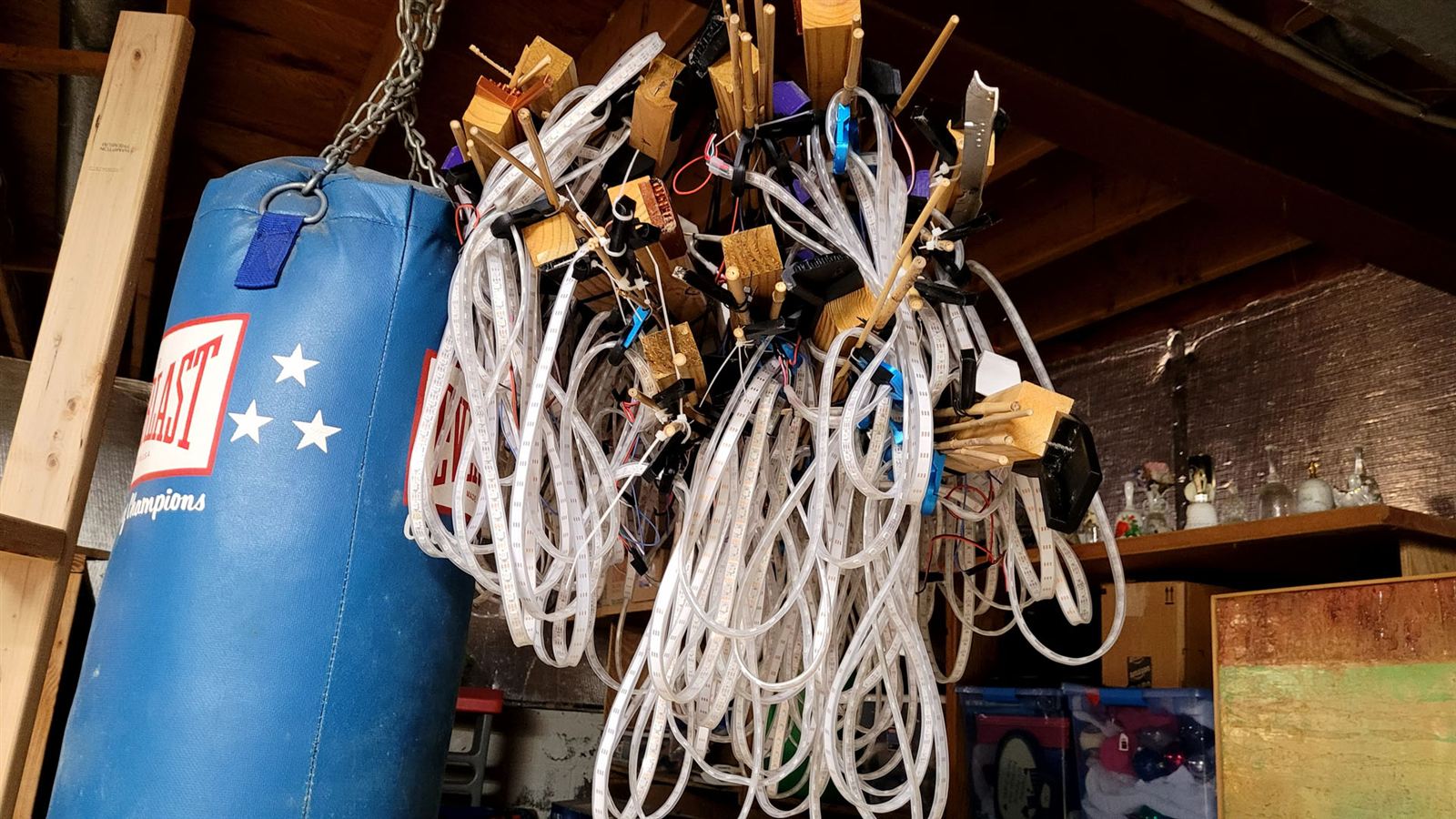
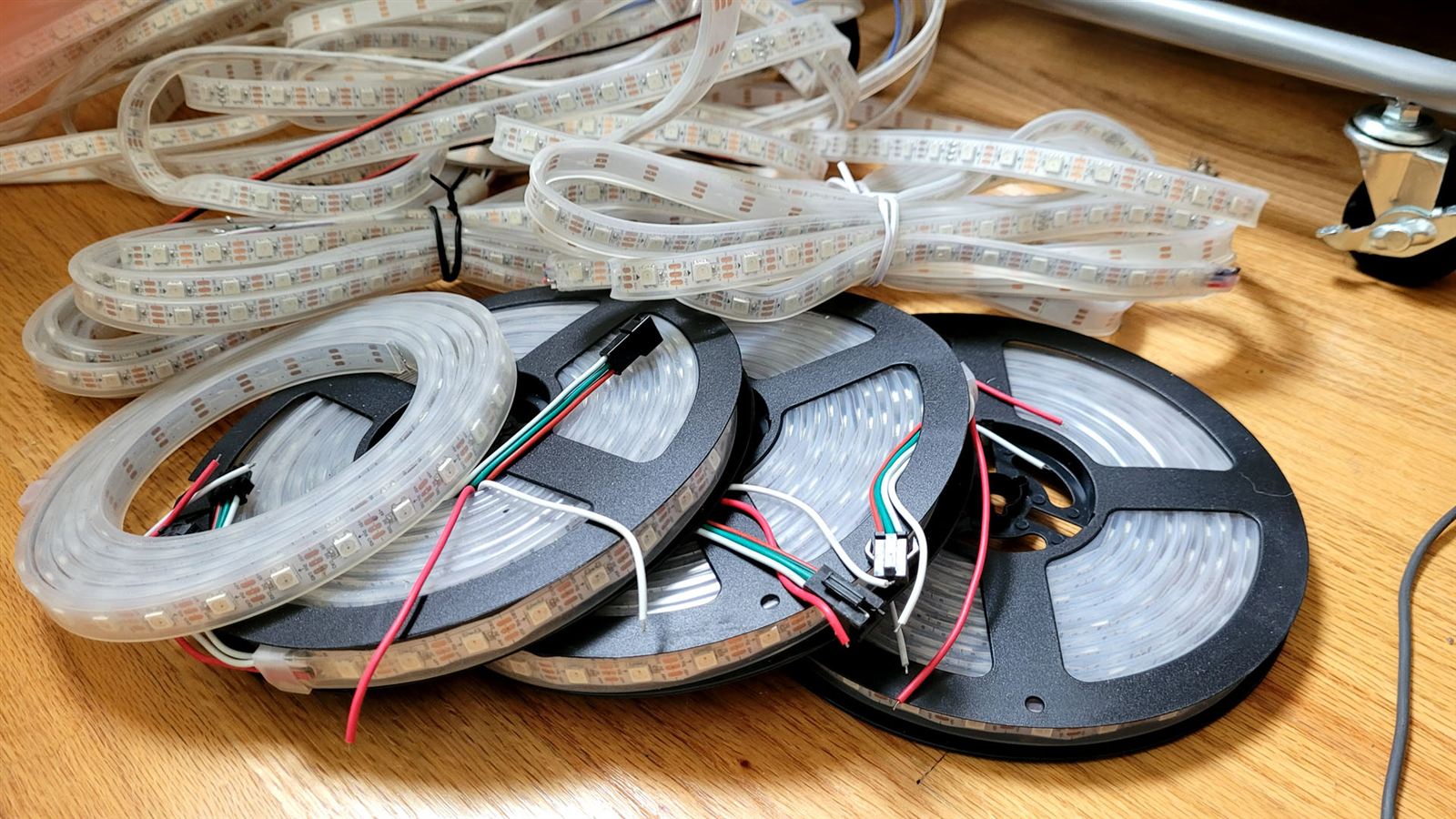
I wanted to go big for the lightshow in the front yard, so I let myself spend $500 for 25 x 5m LED weather-shielded strips. I bought another ten the following year as I needed to replace some strips that had not survived the harsh winds and melting snow. Since the ring I built is 2.5m tall, I had to cut the strips, solder my own leads, and seal the ends with silicone.
Powering all these lights was no small feat. At full brightness, the whole ring could draw perhaps 100A at 5 volts. Fortunately, the difference in brightness from 80% bright to 100% bright was almost imperceptible, and the current draw at 80% was around half the full-bright draw. I put in a software limit that the system never instructs full bright.
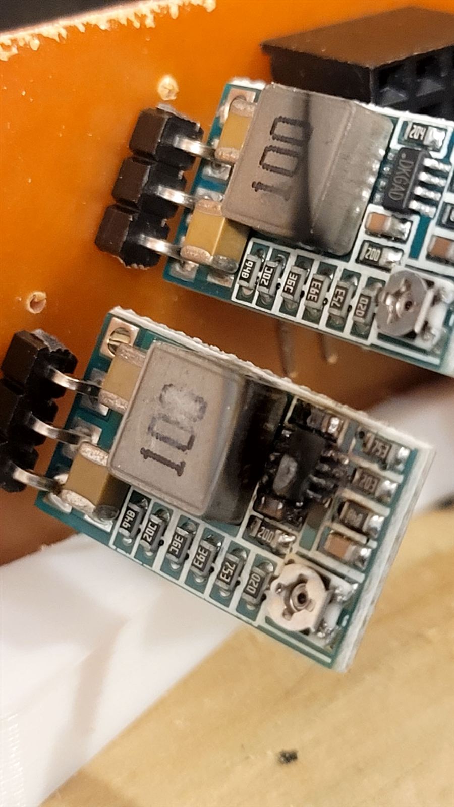
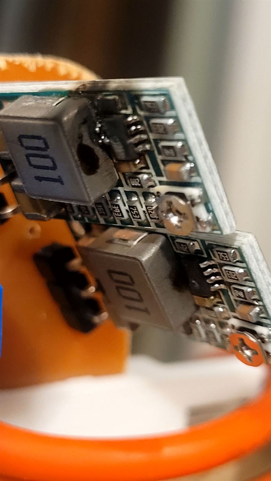
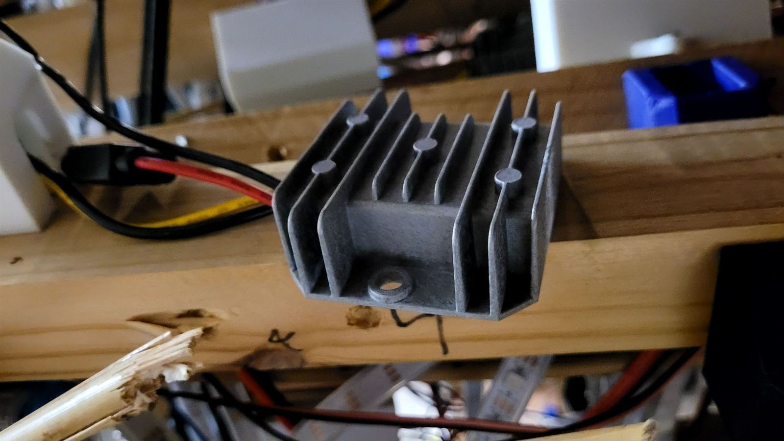
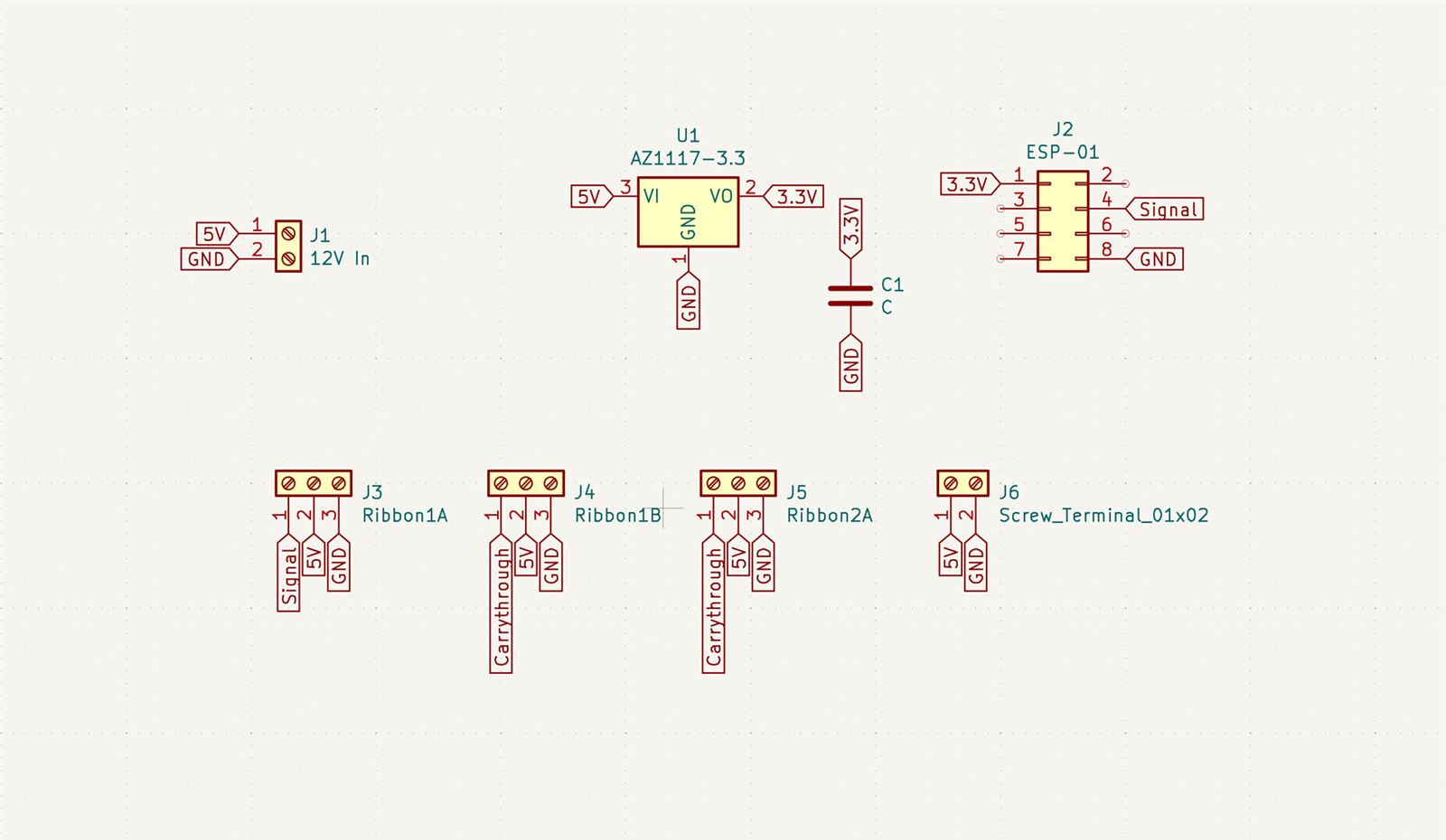
I bought three 80A 12V power supplies, and intended on running the ring off two, with the third as a backup for when something inevitably went wrong. But with the 80% brightness fix, the whole ring runs happily off one 12V supply. The LEDs need to be fed at 5V, and the ESP-01 needs solid juice at 3.3V. I eventually had to buy a dozen high quality 5V all-weather regulators, and the 3.3V draws off the 5V supply with a LDO regulator.
Structurally, I used four 9’ tall fence posts to hold the ring up in the air. Some strips of pressure treated planks at the top and little bamboo sticks for the three lower horizontal braces. The scaffolding is woefully underengineered, it turns out. A smart person would have used two bamboo sticks!
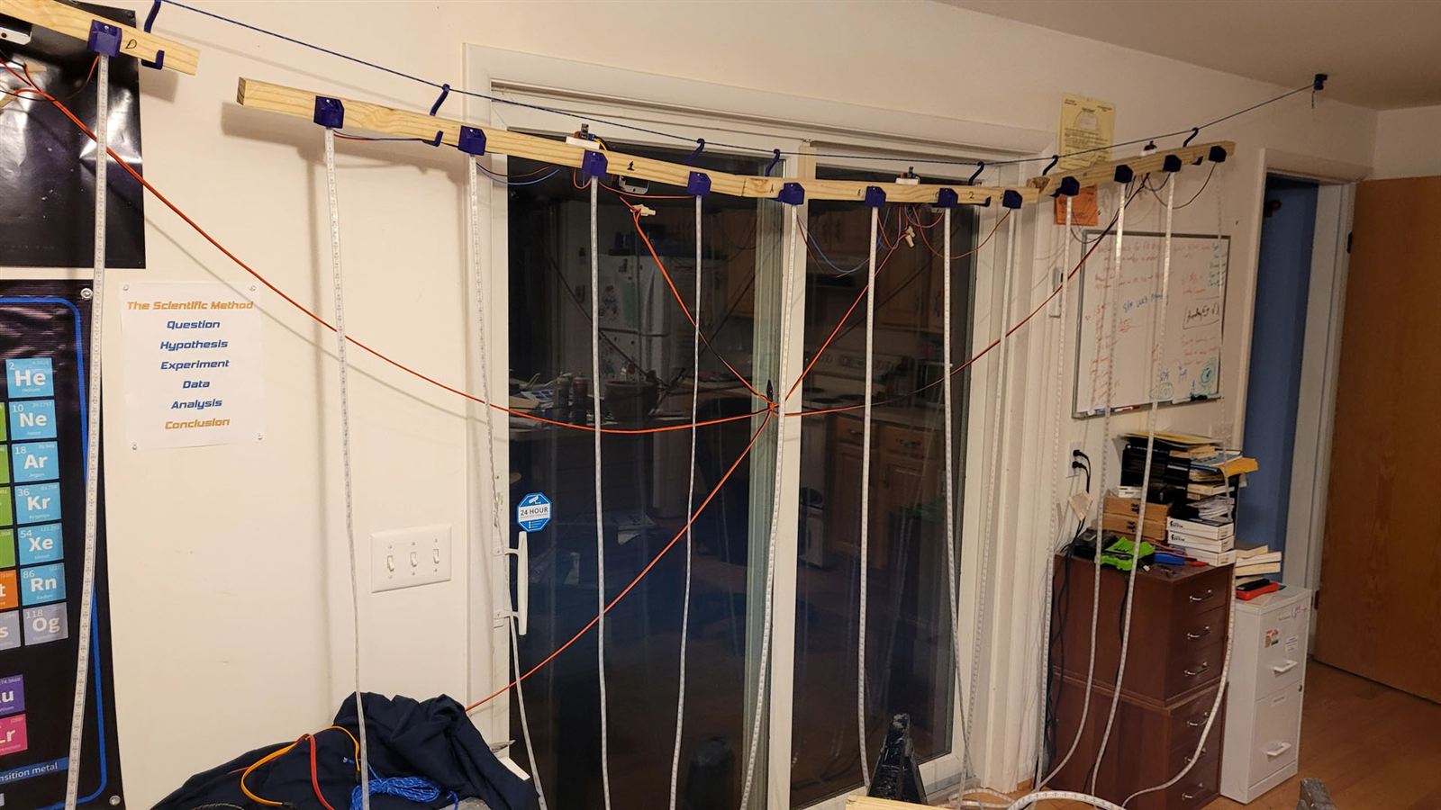
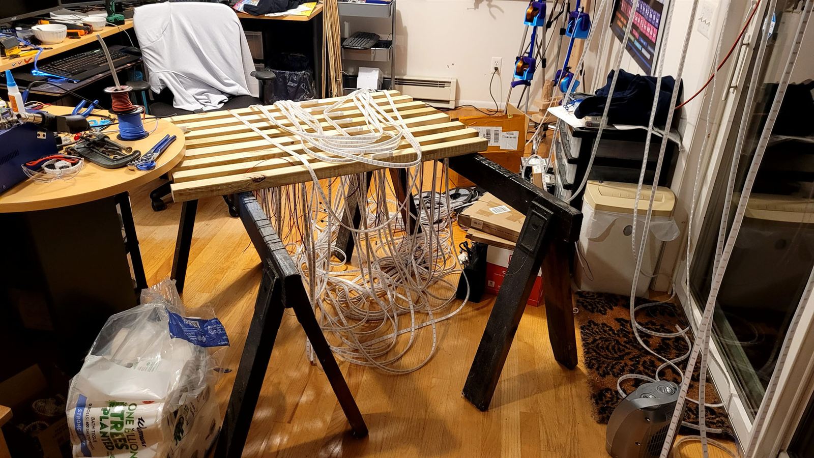
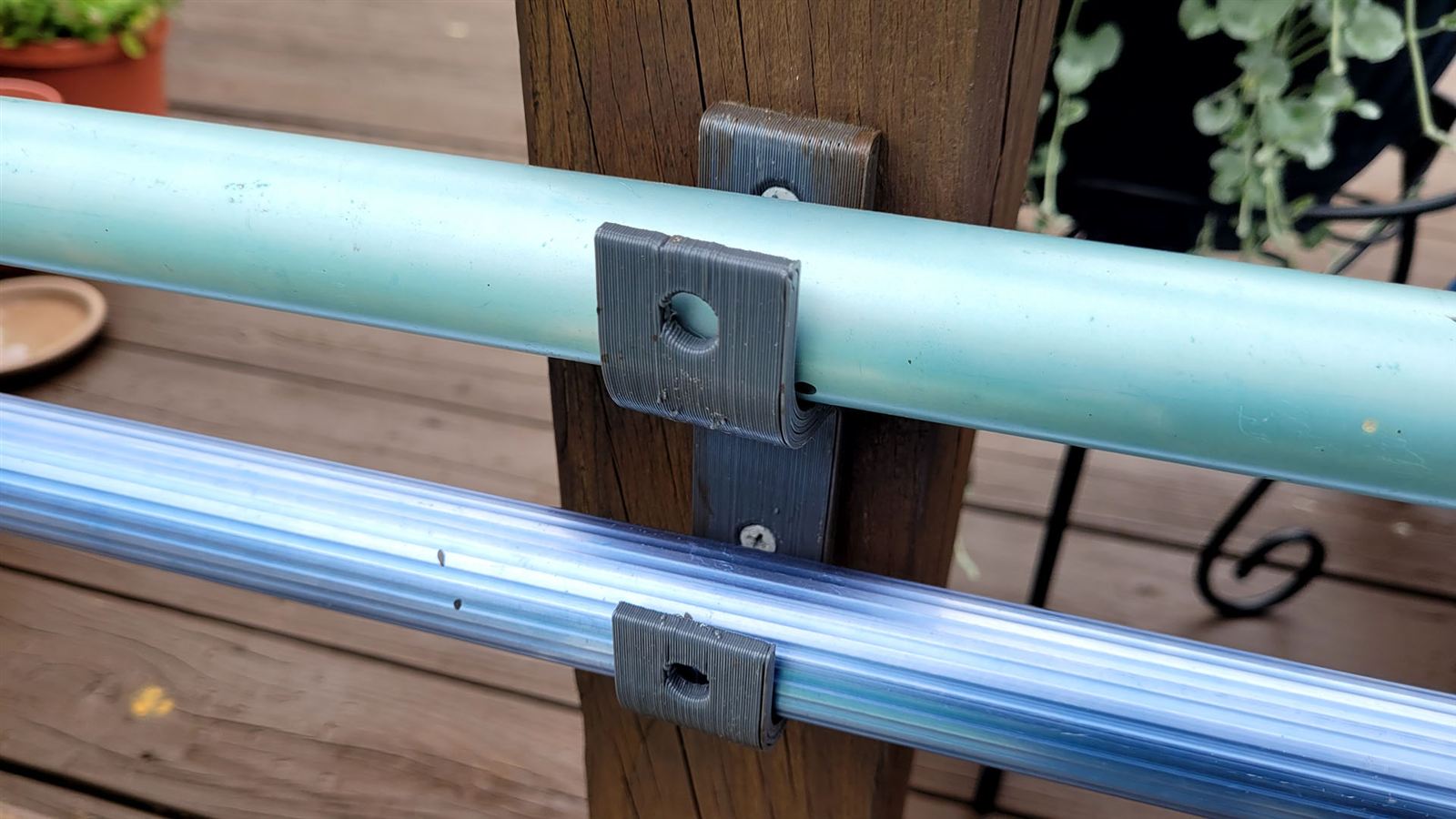
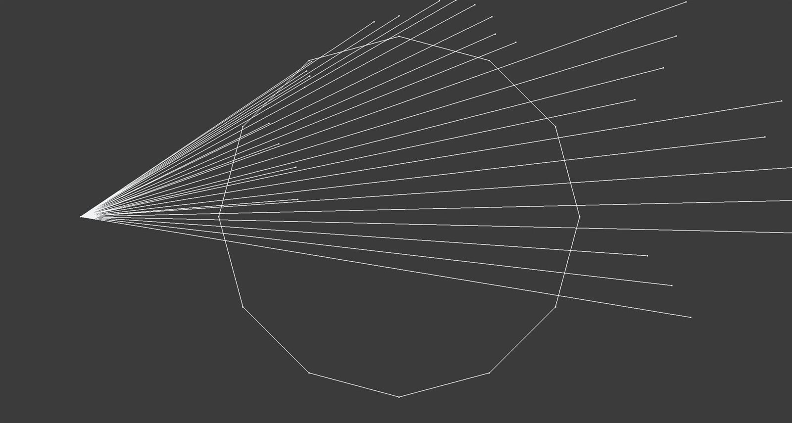
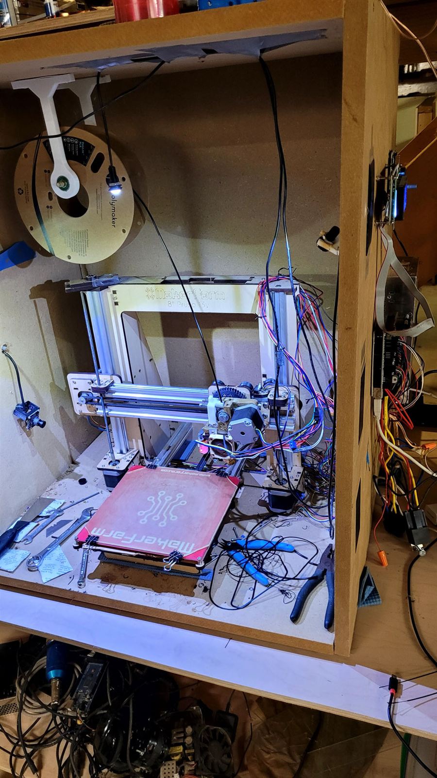
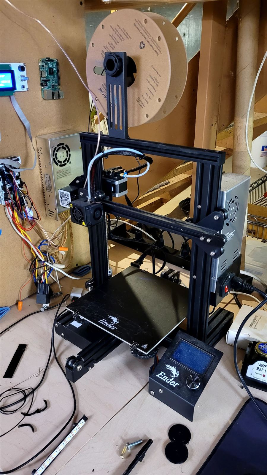
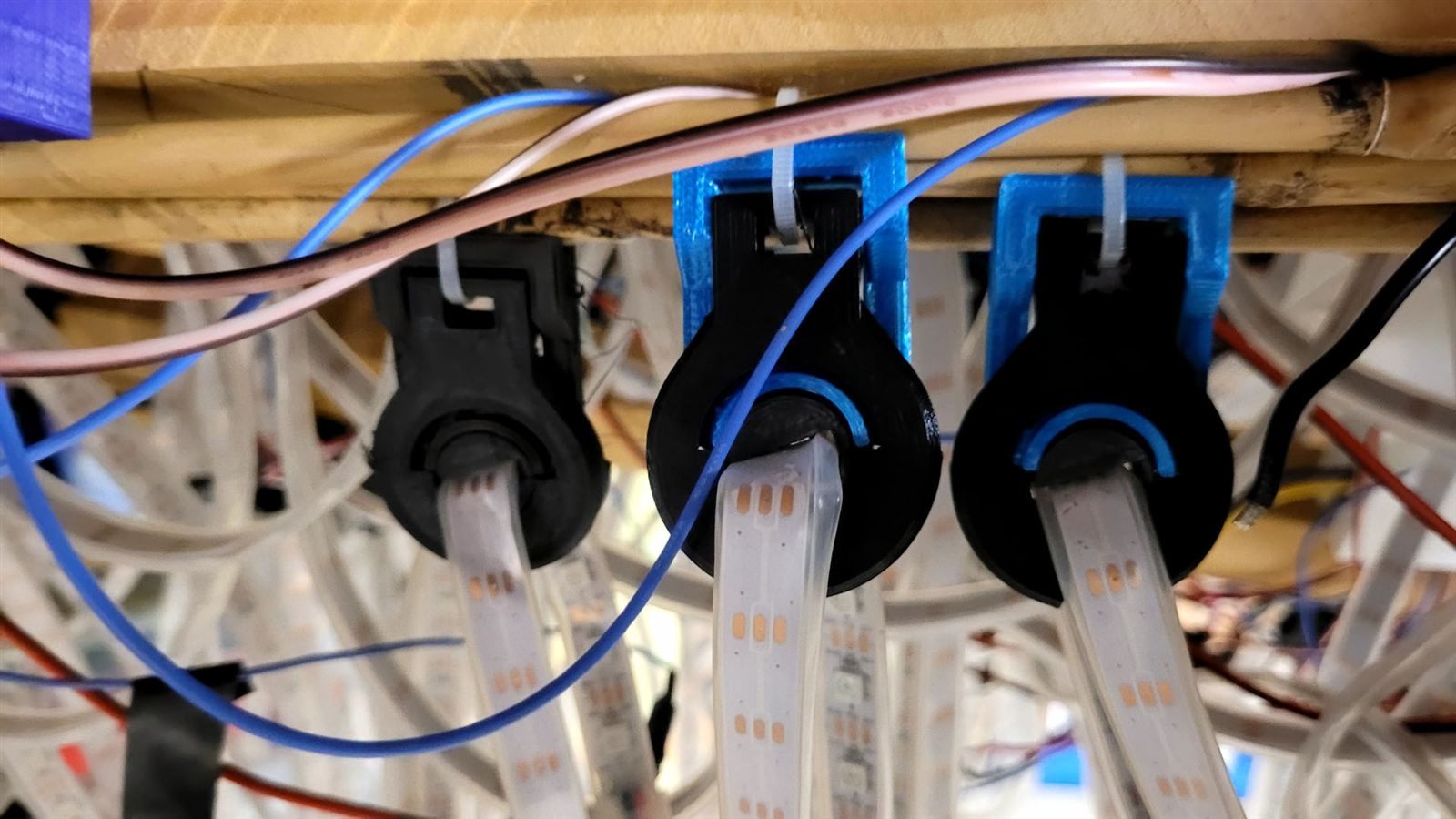
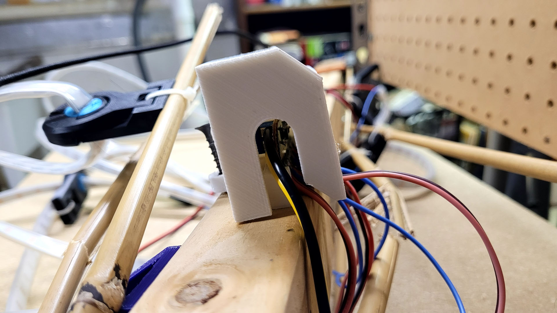
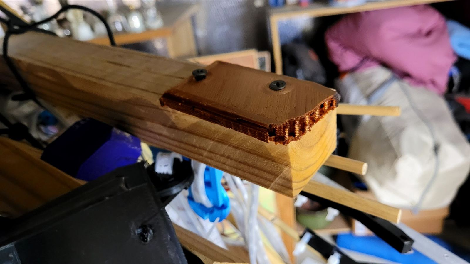
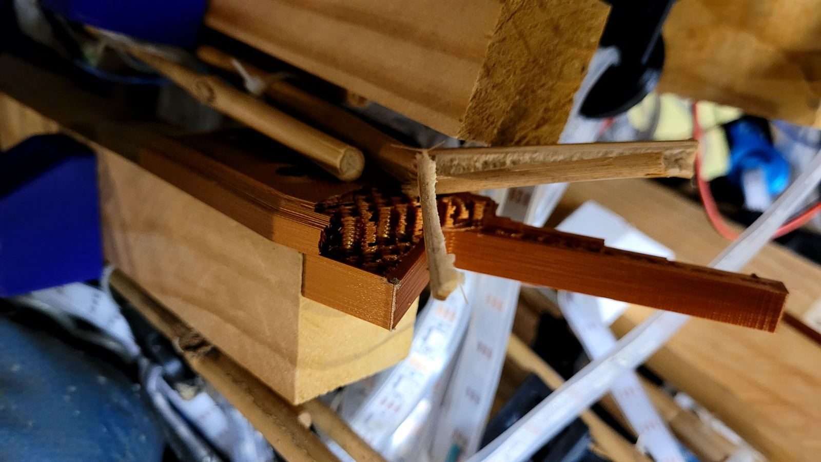
Try to imagine the worst possible way to attach the LED strips to the scaffolding. Got a picture of it in your head? Yep, that’s what I did. I designed a 3D printable system to allow each strip to be independently oriented so the strips would provide “the best view” to passing cars. Each attachment to bamboo was a three piece “spaceship”, and the top attachments were a four piece system. Each bamboo section attached to the fence post via a 3D printed bracket, and the ends of the bamboo and pressure treated segments attached to each other with more 3D printed segments. Each ESP-01 and board was protected by a 3D printed hat, too. With 12 panels of 4 drops per panel, this means I had to 3D print 684 individual parts. My main 3D printer was taking too long so I bought the cheapest Ender 3 I could find to help shoulder the load. The Ender3 is actually a really solid machine – worked beautifully right out-of-the-box.
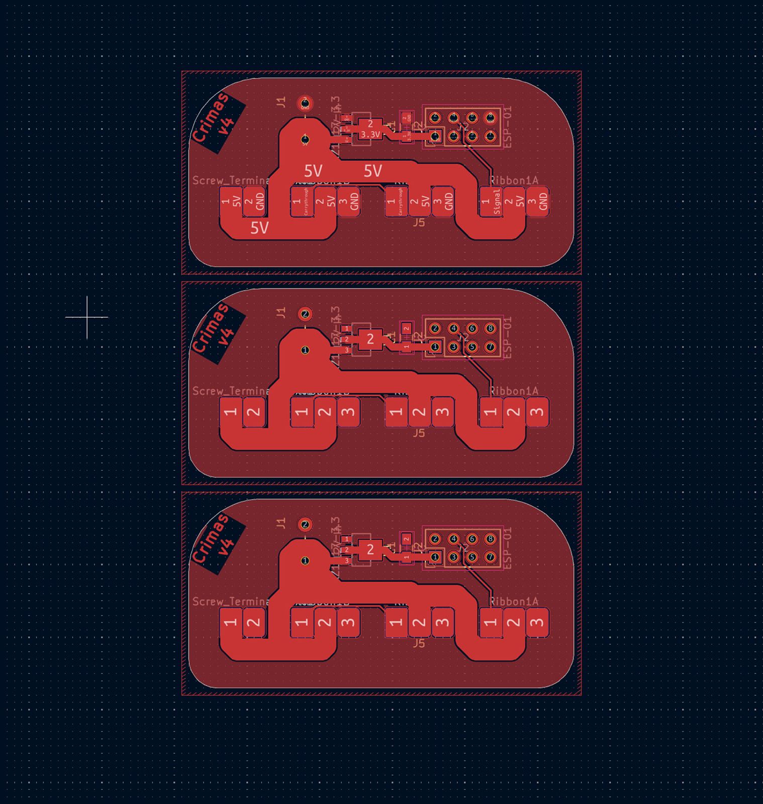
To make the connections to the ESP-01, its 3.3V regulator, and the 5V power and data lines running to the LED strips more manageable, I designed and cut 12 custom PCBs on my homemade CNC router — the FerrousCNC, Exhibit Nº 1.
I programmed up a little website to drive the whole thing, which also served as practice making a Razor Pages website, which I had not really done before. The website runs the physics simulation on a background thread, and reads the parameters that govern the environment of the simulation from settings that can be controlled in real-time. The settings page quickly became a monstrously overwhelming mass of input controls. None of my neighbors dared to fiddle with the settings directly, but stuck to switching between presets I had pre-made. If idle for 15 minutes, the system will switch to another preset at random, with some being suitable for daytime and others for late night. The ring automatically decreases the max brightness based on the time of day so it doesn’t blast my neighbors all night long.
Perhaps my biggest mistake (ok, this whole thing was probably a big mistake) was not knowing I needed to connect the +5 and GND wires at the bottoms of the RGB drops. I only connected the data wire, letting the +5 and GND flow down from the top of the strip. This was a problem because bright LEDs would pull the GND up above 0V and pull the +5V down as we move farther from the supply point at the top of each strip. If one strip had lots of bright lights, and the next didn’t, a data signal that looks like solid 1s and 0s to the bottom of one strip might read all 1s to the next strip. And when it got the signal to do all 1s, everything went full 100% bright, which pulled up the ground even farther, making the strip get stuck in all on ultrabeam infinity brightness mode. A UPS driver handed me a package and told me that my lights were triggering his epilepsy when he was delivering to our street a few nights earlier. Not the desired viewer experience. Connecting 5V and GND at both ends of the strip finally eliminated the flickering nightmare brightness problem.
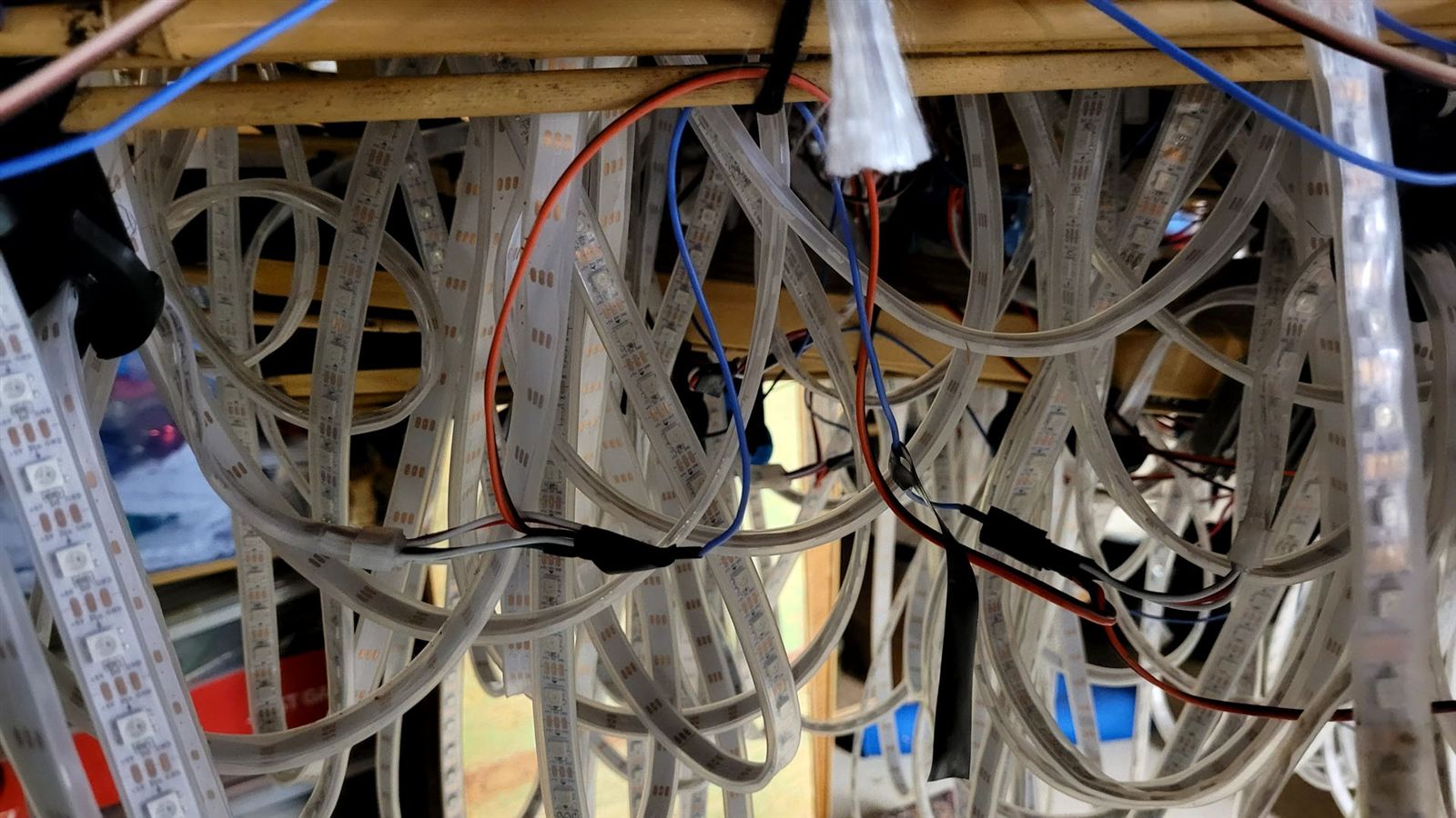
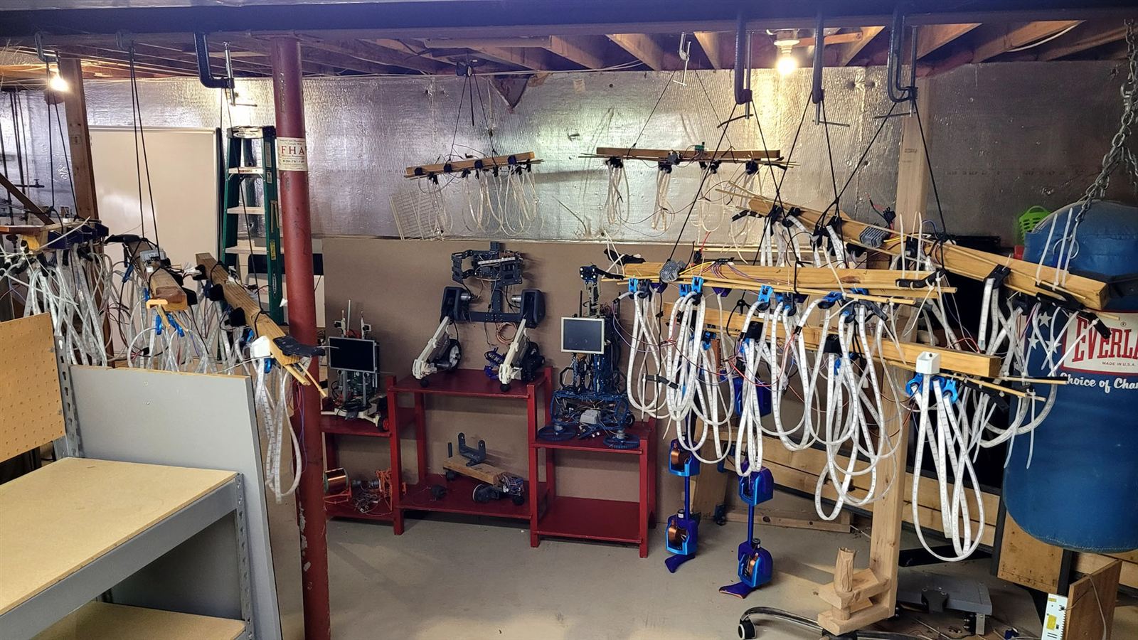
Wind. Wind was rough. It would make the strips fold up, sometimes cracking the thin conductor ribbon inside the flexible PCB ribbon. Then I’d be stuck cutting into the middle of a strip, splicing in a segment of a few LEDs, and then sealing it again with silicone – which was terrible. The second year (2025-2026 winter season), a big wind storm right after New Year’s pulled over one of the posts, snapping the bamboo rods and leaving the light ring in a pitiful way. I dismantled the ring for the year about a month earlier than I planned.
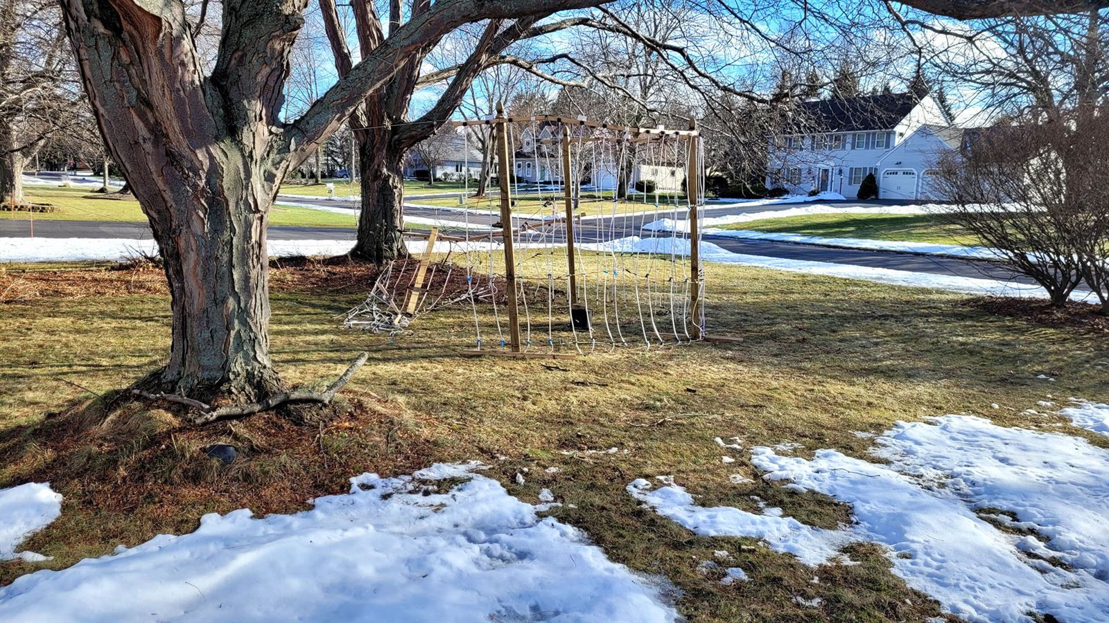
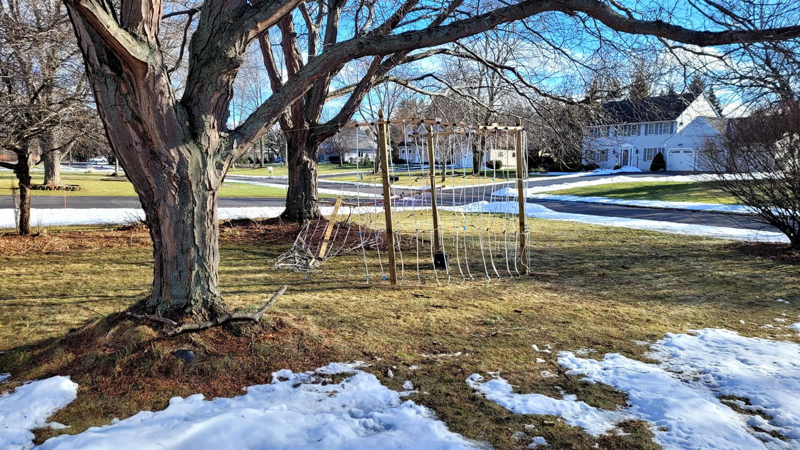
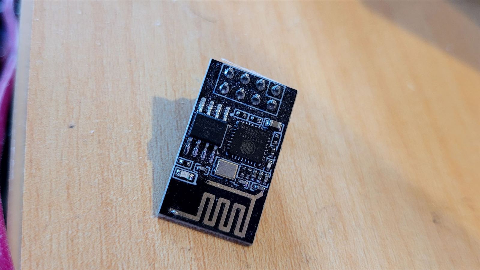
The ESP-01s work great until there’s a lot of them. With 6 panels running (6 little WiFi devices) everything runs smoothly at 30+ FPS. Once I add the other 6 devices, at least three devices will start tripping on all the noise and their FPS will drop to 1 or 2 FPS, and sometimes get stuck looping the old set of frames. With Claude’s help, perhaps I can find the spot where my firmware can be tightened up, and we can get 12 or more panels to stream their color updates in lockstep at 30FPS consistently.
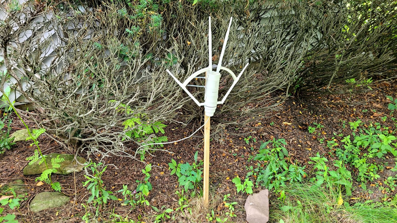
This was a super fun project to do. I loved seeing it changing a bunch because one of my neighbors was pushing buttons on the website. The physical ring comes back with the snow, but the simulator never sleeps. The website runs year-round, and has a page that shows the live state of the panels, whether they’re connected or not. Feel free to hop in and mess around. There are guardrails all around the system so you can’t command it to burn anything out. It can run full white, max brightness continuously (because it gets scaled before it goes out to the panels) so you don’t have to be afraid you’ll mess anything up. There’s also buttons to reset the whole sim, if you’ve messed up the physics and don’t know what setting needs to be changed.
I hope you have a similar project you’re getting ready to tackle. Good luck to you!